Buck-boost Converter Efficiency Calculation
This application note explains power loss factors and methods for calculating them. efficiency of the converter eg.

Efficient Buck Boost Converter Ideal For Power Saving Modes And Wide Input Voltage Ranges
5 66 10 133 20 and 266.

Buck-boost converter efficiency calculation. In particular in the converter topologies like buck boost flyback. Must use Open Delta. Basic Calculations of a 4-Switch Buck-Boost Power Stage 1 Basic Configuration of a Buck-Boost Converter Figure 1 shows the basic configuration of a buck-boost converter where the switches are integrated in the IC.
Estimated 80 The efficiency is added to the duty cycle calculation because the converter has to deliver also the energy dissipated. Design Calculations for Buck-Boost Converters. Basic Buck Boost Equations For calculating inductors in buck boost SMPS circuits we could derive the following two concluding formulas for a buck converter and for a boost converter respectively.
Buck Switching Converter Design Equations. It was last updated on Jun 13 2013. The converter uses a transistor switch typically a MOSFET to pulse width modulate the voltage into an inductor.
To calculate the DCDC buck-boost converter efficiency at any output voltage given that the power supplys efficiency is known at any other output voltage. 80 which is not unrealistic for a. Many of the Advanced Low Power buck-boost converters TPS63xxx have all four switches integrated in the IC.
Boost Converter Efficiency Through Accurate Calculations. Use either an estimated factor eg 90 which is not unrealistic for a buck converter worst-case efficiency or see the Typical Characteristics section of the data sheet of the selected converter. The efficiency calculations shown in the literature.
Also accurate results can be found by this. Single Phase or Three Phase Application. Consuming only microwatts of power this 5V-to-15V boost converter provides low load currents with high efficiency.
Vo DVin ---------- For Buck Converter Vo Vin 1 D ---------- For Boost Converter. Sliding mode controller for PWM based Buck-Boost converter using state space averaging model has been designed and discussed. Portable battery-operated electronic equipment is becoming packed with more features requiring larger amounts of power leading to decreased.
Figure 1 shows the basic configuration of a buck-boost converter where the switches are integrated in the IC. To further improve their efficiency it is helpful to understand the basic mechanism of power loss. This calculation gives a more realistic duty cycle than just the formula without the efficiency factor.
This guide was first published on Jun 13 2013. Efficiency of Buck Converter Switching regulators are known as being highly efficient power sources. Many of the Advanced Low Power buck-boost converters TPS63xxx have all four switches integrated in the IC.
1 Basic Configuration of a Buck Boost Converter. Identifying all of the individual loss contributorsenables the development of higher-order models for designing efficient boost-converter circuits. The buckboost converter is a type of DC-to-DC converter that has an output voltage magnitude that is either greater than or less than the input voltage magnitude.
The buck converter is a high efficiency step-down DCDC switching converter. This calculation gives a more realistic duty cycle than just the equation without the efficiency factor. Rectangular pulses of voltage into an inductor result in a triangular current waveform.
Two different topologies are called buckboost converterBoth of them can produce a range of output voltages ranging from much larger. This spreadsheet will calculate the values of the power stage components for a Buck switchmode power converter. Basic Calculation of an Inverting Buck-Boost Power Stage However most of the converters are already optimized for specific inductance ranges which are described in the data sheet.
The following is a design tool which calculates the parameters for a buck converter boost converter or Buck-Boost Converter - Step-downStep-up or invertingThe calculator assumes that during the normal load the inductor is in continuous mode meaning that the inductor never fully discharges its current. Switching Converter Power Supply Calculator. In most DC-DC converters the normal supply currents do not allow high efficiency at low load currents.
So this provides a quick and easy method to calculate the efficiency of a buck-boost converter at different conditions other than what is given by the standard tables and characteristics in datasheets. Homework Statement Consider a Buck-Boost converter. If in addition to the transistor on resistance R_ON the converter diode has a voltage drop V_D_0 symbolically derive an expression for the efficiency of the converter where .
In this case use the recommended value and calculate the inductor current ripple. Use Open Delta if only need three wires for load. The efficiency is 90 for load currents between 1mA and 8mA.
The user need only to fill in the input voltage output voltage load current switching frequency forward voltage drop of the rectifier and the on resistance of the switch. The efficiency can be calculated as below wihout the loss caused by driver and controller a Pin VinIin average b Pout. Either an estimated factor eg.
It is equivalent to a flyback converter using a single inductor instead of a transformer. This page The Calculator was last updated on Aug 20 2021. Buck Boost Electronic Calculator Calculates proper Square D Transformers to use when doing small changes in voltage.
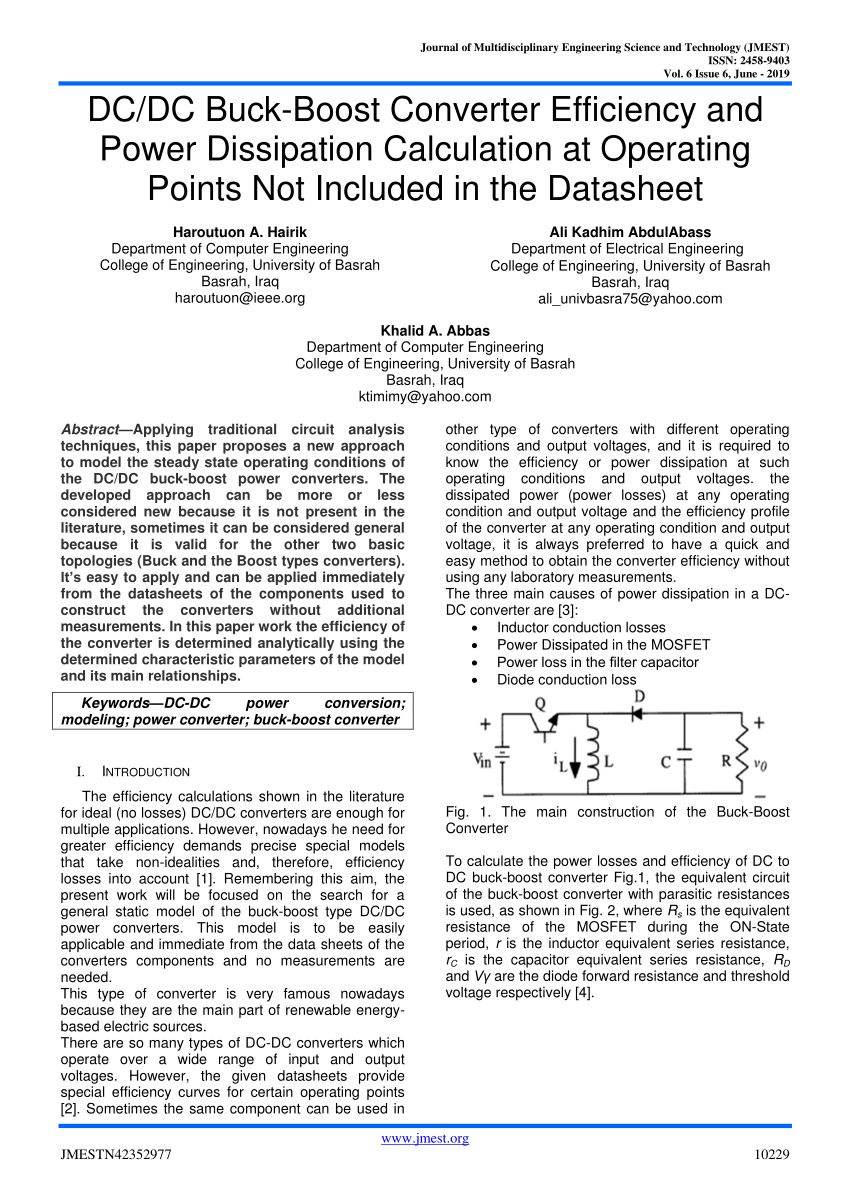
Pdf Dc Dc Buck Boost Converter Efficiency And Power Dissipation Calculation At Operating Points Not Included In The Datasheet

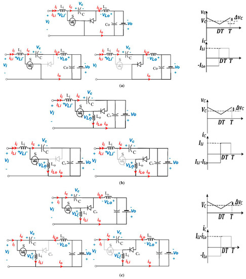
Some Properties Of Buck Boost And Buck Boost Converters Download Scientific Diagram
Energies Free Full Text Continuous Input Continuous Output Current Buck Boost Dc Dc Converters For Renewable Energy Applications Modelling And Performance Assessment Html
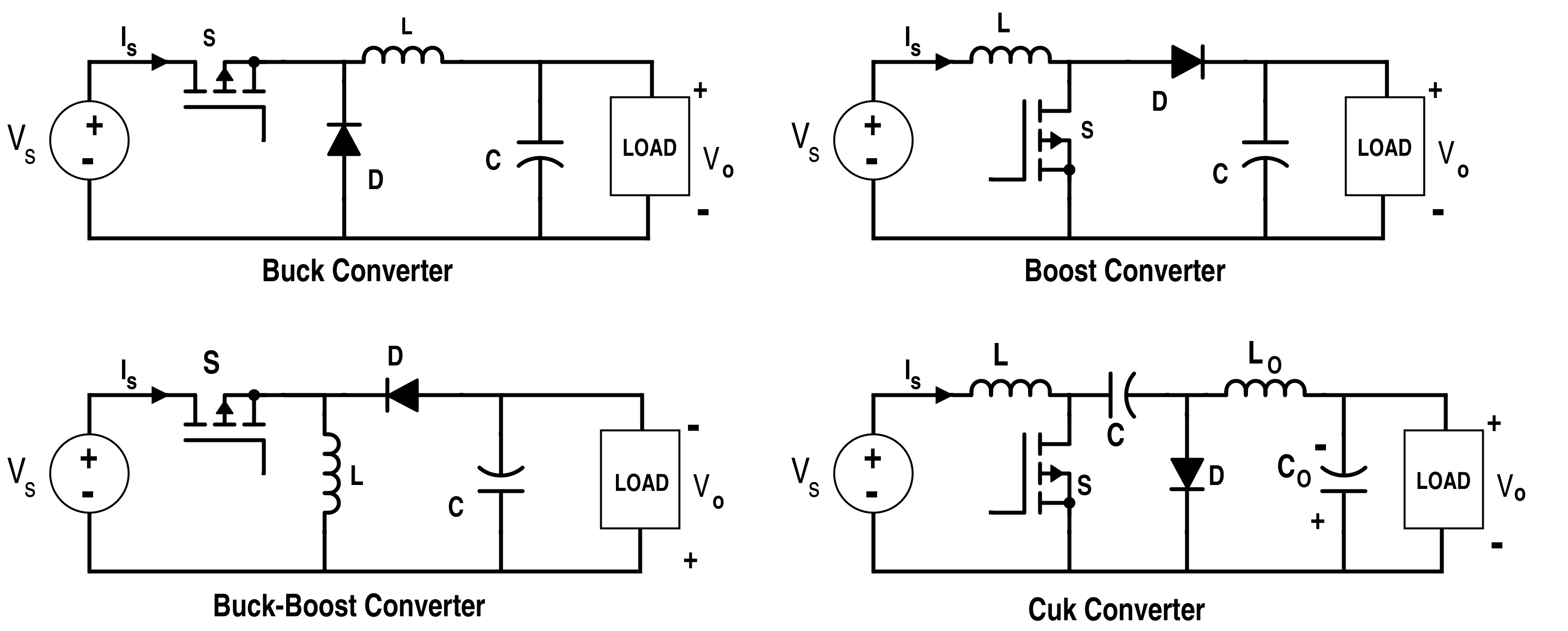
Analysis Of Four Dc Dc Converters In Equilibrium Technical Articles

A Buck Boost Dc Dc Converter B Cuk Dc Dc Converter C Sepic Download Scientific Diagram
Buck Boost Converter Analysis
Https Www Ti Com Seclit Ml Slup346 Slup346 Pdf

Some Properties Of Buck Boost And Buck Boost Converters Download Scientific Diagram

15v 2 5a Monolithic Buck Boost Dc Dc Converter With 95 Efficiency And Low Noise Operation

Parameters Of Dc Dc Buck Boost Converter With A Cpl Download Table

How To Apply Dc To Dc Step Up Step Down Regulators Successfully Analog Devices

Synchronous Inverse Sepic Topology Provides High Efficiency Buck Boost Voltage Converters Analog Devices

A Topology Of H Bridge For The Buck Boost Converter And B Energy Download Scientific Diagram
Inductor Voltage And Current Of Buck Boost Converter In Pccm Download Scientific Diagram
Asian Economic And Social Society
Dc To Dc Buck Boost Converter Circuit Homemade
Power Electronics Lecture10 D C To D C

How Does Buck Boost Converter Work Quora

Summaries Of The Operation Of The Buck Boost Converter Download Table
Post a Comment for "Buck-boost Converter Efficiency Calculation"