Buck Converter Efficiency Measurement
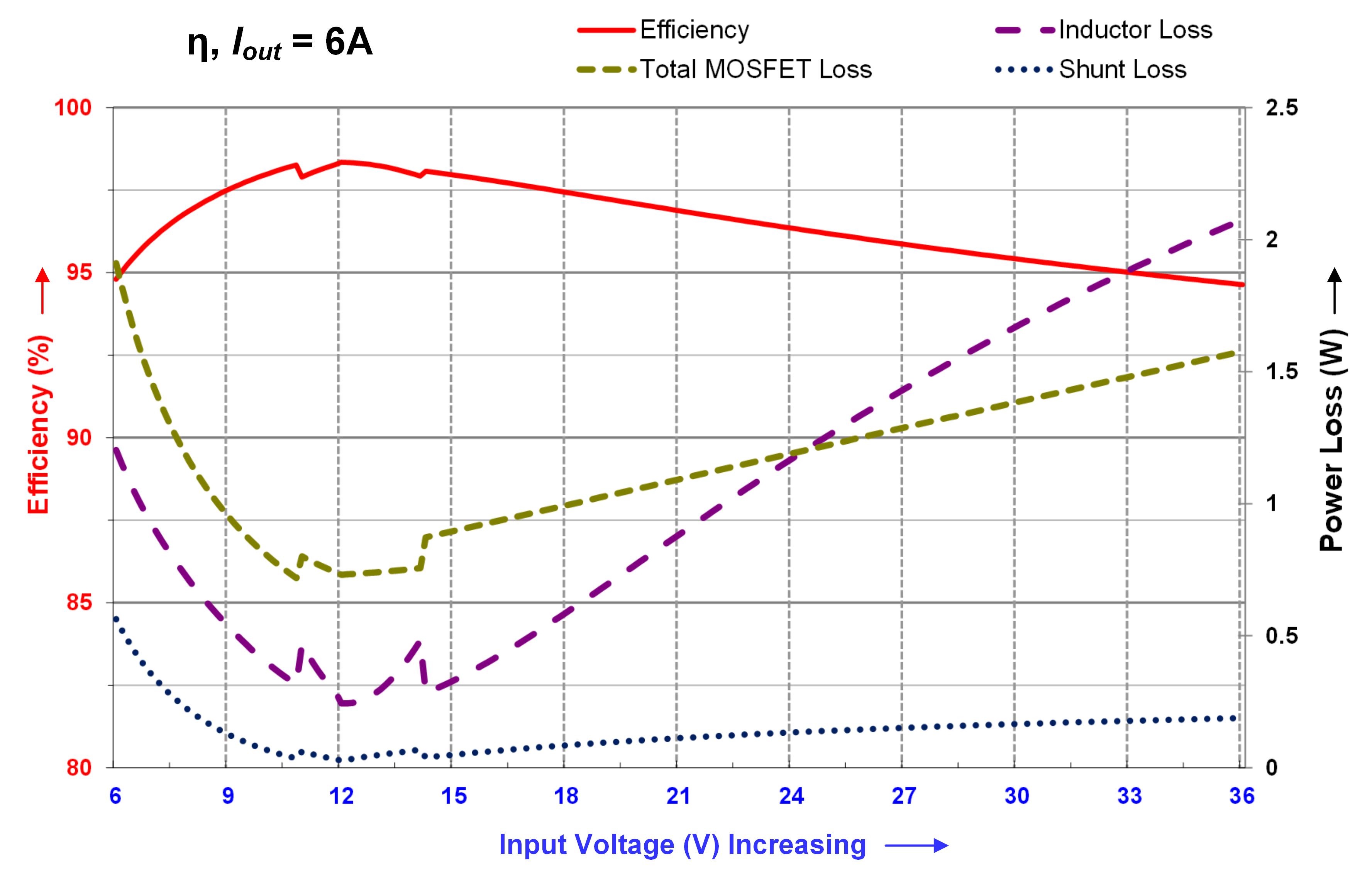
The dominant losses in a buck converter design depend on. Figure 22 shows the key component loss in.
Do Not Operate A 4 Switch Buck Boost Converter In Buck Boost Mode Power Management Technical Articles Ti E2e Support Forums
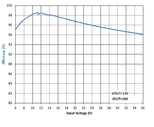
It provides a fixed 15-V output at up to 20 A from a 12-Vinput bus.
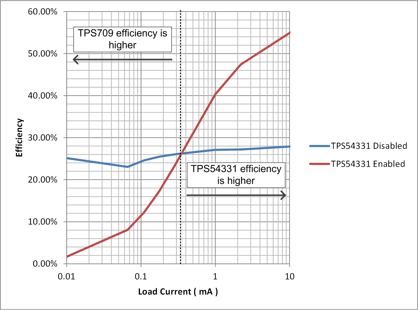
Buck converter efficiency measurement. Youll see this kind of fancy footwork in IC datasheets. Determine Buck Converter Efficiency in PFM Mode By analyzing the light-load efficiency of a synchronous buck operating under pulse frequency modulation control designers can predict efficiency over the converters full load range and maximize battery life in portable applications. Buck Converter Background.
You have to measer the DC current in which means you need to install a L-C filter. The PV array which is to be used with this system giving a 50 W maximum power and an 216 V open circuit voltage at an irradiation of. In particular in the converter topologies like buck boost flyback.
Measuring efficiency of buck-boost converter using with and without modified perturb and observe po mppt algorithm of photo-voltaic pv arrays Md. This spreadsheet will calculate the values of the power stage components for a Buck switchmode power converter. The TPS53353 is a D-CAPmode 20-Asynchronous buck converter with integrated MOSFETs.
The loss calculation also compares with real buck converter measurement and provides the key component loss data to consider how to improve the buck converter efficiency. Prototype MPPT system has been developed for Buck-Boost converter using the above described methods and tested experimentally. Synchronous buck converters have received great attention in low voltage DCDC converter applications because they can offer high efficiency.
Khaliluzzaman INTRODUCTIONSolar photovoltaic array PV is becoming an increasing attractive way to generate power around the. The simplest efficiency measure is wallplug efficiency - IOUTVOUTIINVIN. The efficiency can be calculated as below wihout the loss caused by driver and controller a Pin VinIin average b Pout.
If you hook the meters up to measure the input and output current then trigger them simultaneously youll be able to compare the results to determine the efficiency assuming the input and output voltages are holding constant. Measuring Input Current of a Buck or Flyback Converter Input currents for non-boost converter topologies can be derived from current measurements in the primary switch. Dec 03 2012 you have to measer the DC current in which means you need to install a L-C filter.
A typical synchronous buck circuit using MOSFETs as a switch is shown in. The parameters to minimize for high efficiency can be quickly determined utilizing these equations. Also the most relevant to the user.
The main construction of the Buck-Boost Converter To calculate the power losses and efficiency of DC to DC buck-boost converter Fig1 the equivalent circuit of the buck-boost converter with parasitic resistances is used as shown in Fig. While the inductor and MOSFETs have 870mW of power loss quiescent power consumption adds just 900W to the total sum. Provide more precise output voltage and also meet the size requirement constraints.
John Bottrill Senior Applications Engineer Texas Instruments Manchester NH. For a buck converter by varying the duty cycle of the switch a desired average voltage output can be achieved. Buck converter efficiency measurement.
He monitors the drive PWM with. Then calculate input power volts times current. 2 where R s is the equivalent resistance of the.
The test setup is simple. As a designer youd want to know more. The user need only to fill in the input voltage output voltage load current switching frequency forward voltage drop of the rectifier and the on resistance of.
You have to get the input current to DC so the meter will read it correctly. Has developed a series of integrated buck regulators SupIRBuckTM to accommodate all the. One of our guys on.
This application document analyzes power loss in synchronous buck converters and presents the detailed calculations for each part of the power loss. Using the TPS53353EVM-744High-Efficiency20-A Synchronous Buck Converter With Eco-modeControl Scheme The TPS53353EVM-744 evaluation module EVM demonstrates the TPS53353. Shows a typical buck converter.
If the input and output voltages are also changing you may need 4 multimeters to get all the information you need. He built a buck converter and made measurements about its efficiency using different configurations. Vendors of components like to de-embed the losses from any component they didnt make.
Measure output voltage and current calculate power. 3Amax Transfer efficiency92max Switching Frequency65KHz Module Size. 9 rnduri Measurement and calculation of efficiency comparison.
A small inductor and a HUGE capacitor at the input pin of the buck converter.
How To Improve Buck Converter Light Load Efficiency With An Ldo Part 2 Power Management Technical Articles Ti E2e Support Forums

Measured Efficiency Curves Of The Buck Converter Download Scientific Diagram

Measured Efficiency Curves Of The Buck Converter Download Scientific Diagram

How To Increase Efficiency And Mitigate Power Loss In Buck Converters Technical Articles
Dc Dc Conversion
Using A Dc Dc Converter To Power An Adc Power Management Technical Articles Ti E2e Support Forums

Buck Converter Wikiwand
Using A Dc Dc Converter To Power An Adc Power Management Technical Articles Ti E2e Support Forums

Choosing The Optimum Switching Frequency Of Your Dc Dc Converter Ee Times
How To Measure The Efficiency Of A Multiphase Buck Converter Integrated Circuit

Efficiency Of Half Bridge Vs Inverter Dc Dc Power Topologies Part 1 Of 2 Ee Times

Power Conversion Efficiency Curves Of The Ac Dc Rectifier Dc Dc Download Scientific Diagram
Increase Dc Dc Converter Efficiency Understanding Operating Modes And Power Losses Power Management Technical Articles Ti E2e Support Forums

How To Increase Efficiency And Mitigate Power Loss In Buck Converters Technical Articles

How To Apply Dc To Dc Step Down Buck Regulators Successfully Analog Devices

Efficiency Measurement Of A Step Down Converter Buck Converter Youtube

Measured Waveforms In The Synchronous Buck Converter Trace 1 Gate Download Scientific Diagram

Efficiency Versus Input Power For Different Dc Dc Converter Topologies Download Scientific Diagram

The Low Power Version Synchronous Buck Converter Efficiency Measurement Download Scientific Diagram
Post a Comment for "Buck Converter Efficiency Measurement"