Buck Converter Power Efficiency Calculation
The efficiency is added to the duty cycle calculation because the converter also has to deliver the energy dissipated. In particular in the converter topologies like buck boost flyback.

Buck Converter Design Tutorial Complete Equation Derivation And Design Sample
I measured the output current by measuring voltage of voltage divider.
Buck converter power efficiency calculation. In this case the input power exceeds the output power by 125W or 20 which is lostwasted power. The parameters to minimize for. Also accurate results can be found by this.
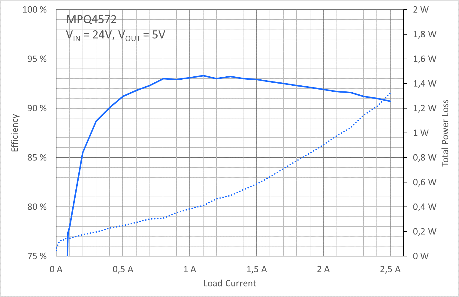
Efficiency calculations are necessary. This is converting 24 vols into 33 vols DC-DC converter. Efficiency of Buck Converter Switching regulators are known as being highly efficient power sources.
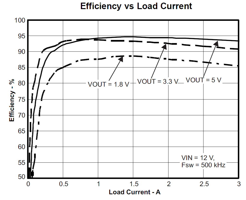
The Buck Converter Page 9 2. The Greek symbol Eta is. In order to check the accuracy of these power loss equations Table1 shows the typical buck converter application parameter and Figure 21 illustrates the efficiency comparison between measurement and calculation.
If the diodes forward voltage drop could be loweredthe converters efficiency could be raised. To illustrate the factors that play a role in a buck converters efficiency the Table below lists the equations used to estimate the most significant power losses. Switching Converter Power Supply Calculator.
Buck Converter Design 7 Design Note DN 2013-01 V01 January 2013 Duty cycle variation based on power losses in high efficiency converters usually has no big impact on the inductor value and can be ignored for inductor selection. Several losses in buck converter must be calculated to estimate the efficiency and losses. This application note explains power loss factors and methods for calculating them.
My input current is about 3278mA. The most common SMPS is the Buck Converter in which the output voltage is always lower than the input. Inductor Calculation for Buck Converter IC This application note covers the steps required in choosing the inductor and to calculate the value used in buck regulator IC circuits.
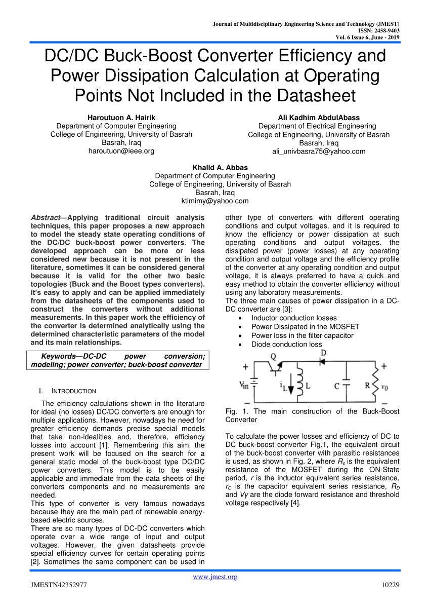
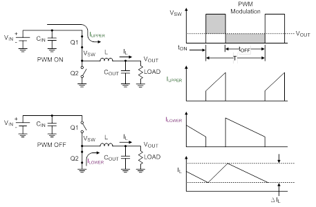
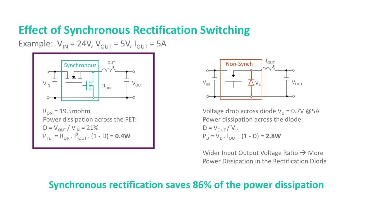
As shown in Figure 1 the synchronous buck converter is comprised of two power MOSFETs an output inductor and input and output. To calculate the DCDC buck-boost converter efficiency at any output voltage given that the power supplys efficiency is known at any other output voltage. So my input power is about 32.
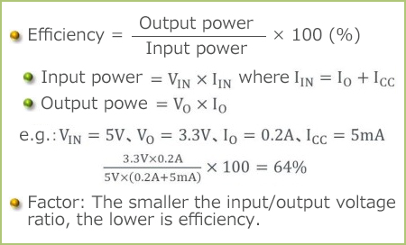
105 wattsEfficiency 10w 10w 105w 905 This Buck converter design example has a calculated efficiency of 905. The efficiency can be calculated as below wihout the loss caused by driver and controller a Pin VinIin average b Pout. Here is the datasheet spec.
TI Buck Switching Solutions 2 Power Losses Calculation for Synchronous Buck Converter Figure 2 shows the power losses of synchronous buck converter including the switching losses the. Then I used 33-124866k0000238mA. A SMPS switched-mode power supply is a nonlinear power converter which holds a high efficiency rate.
The diode losses represent almost one half of the total losses. This buck converter design example is called an Asynchronous Buck converter because the diode. So this provides a quick and easy method to calculate the efficiency of a buck-boost converter at different conditions other than what is given by the standard tables and characteristics in datasheets.
To further improve their efficiency it is helpful to understand the basic mechanism of power loss. A power converters efficiency AC-DC or DC-DC is determined by comparing its input power to its output power. Buck Step-Down Converter Switching regulators are used in a variety of applications to provide stable and efficient power conversion.
My efficiency is PoutPin 0009. Power loss measurement and calculation comparison Although the buck converter power loss calculated equations are well introduced and documented. It also explains how the relative importance of power loss factors depends on the specifications of the switching power source.
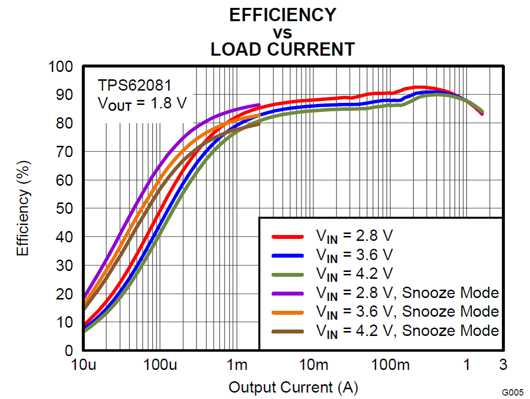
Buck converters can be highly efficient often higher than 90 making them useful for tasks such as converting a computers main bulk supply voltage often 12 V. The efficiency is not fixed but changes according to the input voltage of the circuit and the load as you can see in the below table table 1. This calculation gives a more realistic duty cycle than just the formula without the efficiency factor.
Switching converters such as buck converters provide much greater power efficiency as DC-to-DC converters than linear regulators which are simpler circuits that lower voltages by dissipating power as heat but do not step up output current. DCDC Buck-Boost Converter Efficiency and Power Dissipation Calculation. For example the efficiency of a converter that provides 500W of output power Pout and requires 625W for the input power Pin would be 80 500W625W080.
The following is a design tool which calculates the parameters for a buck converter boost converter or Buck-Boost Converter - Step-downStep-up or invertingThe calculator assumes that during the normal load the inductor is in continuous mode meaning that the inductor never fully discharges its current. This paper proposes a new approach to model the steady state operating conditions of the DCDC buck-boost power converters. More precisely the efficiency of the converter is calculated by dividing the output power Pout by its input power Pin.
Practically a 150nH inductor will have to. Under these conditions the efficiency of the buck converter with the LTC1707 is 9578. A SMPS is a circuit in which AC is rectified and converted into DC unregulated.
A synchronous buck converter produces a regulated voltage that is lower than its input voltage and can deliver high current while minimizing power loss. Use either an estimated factor eg 90 which is not unrealistic for a buck converter worst-case efficiency or see. This application note gives the formulas to calculate the power stage of a synchronous buck operating in continuous conduction mode.
Efficiency And Thermal Calculation Basic Knowledge Rohm Tech Web Technical Information Site Of Power Supply Design

How To Increase Efficiency And Mitigate Power Loss In Buck Converters Technical Articles
A Perfect Match Power Losses In Buck Converters And How To Increase Efficiency Article Mps

Buck Converter Design Tutorial Complete Equation Derivation And Design Sample

Buck Converter Design Tutorial Complete Equation Derivation And Design Sample
Basic Calculation Of A Buck Converter S Power Stage Richtek Technology

Typical Ac Dc And Dc Dc Conversion Efficiency Curves Download Scientific Diagram
Power Electronics Notes 07b Some Real World Issues In Dc Dc Converters Ppt Download
Understanding Power Losses In Buck Converters Youtube

Buck Converter Design Tutorial Complete Equation Derivation And Design Sample
Using A Dc Dc Converter To Power An Adc Power Management Technical Articles Ti E2e Support Forums

Efficiency Calculations For Power Converters Edn
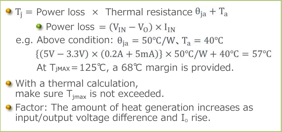
Efficiency And Thermal Calculation Basic Knowledge Rohm Tech Web Technical Information Site Of Power Supply Design
Using A Dc Dc Converter To Power An Adc Power Management Technical Articles Ti E2e Support Forums

Need To Estimate Buck Converter Efficiency In Portable Apps Ee Times

An 140 Basic Concepts Of Linear Regulator And Switching Mode Power Supplies Analog Devices

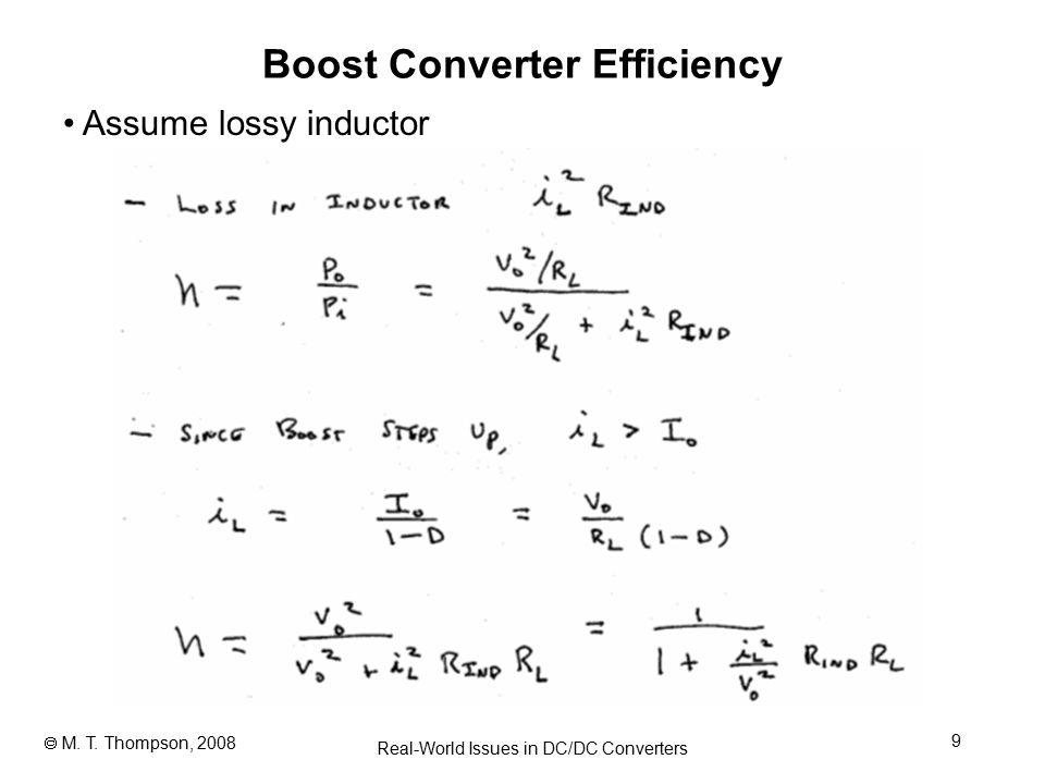
Boost Converter Efficiency Through Accurate Calculations Power Electronics
Pdf Dc Dc Buck Boost Converter Efficiency And Power Dissipation Calculation At Operating Points Not Included In The Datasheet

Power Conversion Efficiency Curves Of The Ac Dc Rectifier Dc Dc Download Scientific Diagram
Post a Comment for "Buck Converter Power Efficiency Calculation"